Flowdrill - Long (Flat)
")
Flowdrill - Long (Flat)
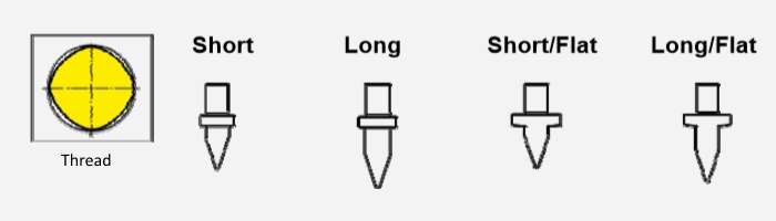
| Thread | Flowdrill Diameter | Short | Long | Short Flat | Long Flat | Total Length of tool's working part | Shank Diameter | |
|---|---|---|---|---|---|---|---|---|
| Short | Long | |||||||
| M=Metric MF=Metric Fine |
[mm] | Maximum Material Thickness | [mm] | [mm] | [mm] | |||
| [mm] | [mm] | [mm] | [mm] | |||||
| M2 | 1.8 | 1.6 | 2.2 | 1.8 | 3.2 | 5.8 | 7.8 | 6 |
| M2.5 | 2.3 | 1.6 | 2.3 | 1.9 | 3.5 | 6.1 | 8.1 | 6 |
| M3 | 2.7 | 1.7 | 2.4 | 2.0 | 3.7 | 6.7 | 8.7 | 6 |
| M4 | 3.7 | 1.8 | 2.6 | 2.2 | 4.2 | 8.1 | 10.3 | 6 |
| MF4x0.5 | 3.8 | 1.8 | 2.6 | 2.2 | 4.2 | 8.2 | 10.5 | 6 |
| M5 | 4.5 | 1.9 | 2.7 | 2.4 | 4.6 | 9.2 | 11.8 | 6 |
| MF5x0.5 | 4.8 | 1.9 | 2.7 | 2.4 | 4.7 | 9.6 | 12.4 | 6 |
| M6 | 5.4 | 2.0 | 2.9 | 2.5 | 5.0 | 10.5 | 13.5 | 6 |
| MF6x0.75 | 5.6 | 2.0 | 2.9 | 2.5 | 5.0 | 11.0 | 14.5 | 6 |
| MF6x0.5 | 5.8 | 2.0 | 3.0 | 2.6 | 5.2 | 11.2 | 14.7 | 6 |
| M8 | 7.3 | 2.2 | 3.3 | 2.9 | 5.9 | 13.5 | 18.1 | 8 |
| MF8x1 | 7.5 | 2.3 | 3.4 | 2.9 | 6.0 | 14.0 | 18.7 | 8 |
| MF8x0.75 | 7.6 | 2.3 | 3.4 | 2.9 | 6.0 | 14.1 | 18.8 | 8 |
| M10 | 9.2 | 2.6 | 3.7 | 3.2 | 6.6 | 16.8 | 22.5 | 10 |
| MF10x1.25 | 9.3 | 2.6 | 3.7 | 3.3 | 6.7 | 17.0 | 22.8 | 10 |
| MF10x1 | 9.5 | 2.6 | 3.8 | 3.3 | 6.7 | 17.3 | 23.2 | 10 |
| M12 | 10.9 | 2.8 | 4.0 | 3.5 | 7.2 | 19.8 | 26.4 | 12 |
| MF12x1.5 | 11.2 | 2.8 | 4.1 | 3.6 | 7.3 | 20.3 | 27.1 | 12 |
| MF12x1 | 11.5 | 2.9 | 4.2 | 3.6 | 7.3 | 20.8 | 27.8 | 12 |
| M14 | 13.0 | 3.0 | 4.5 | 3.9 | 7.9 | 23.5 | 31.3 | 14 |
| MF14x1.5 | 13.2 | 3.1 | 4.6 | 4.0 | 8.0 | 23.8 | 31.6 | 14 |
| M16 | 14.8 | 3.3 | 4.8 | 4.2 | 8.5 | 26.9 | 35.4 | 16 |
| M16x1.5 | 15.2 | 3.4 | 4.9 | 4.3 | 8.7 | 27.6 | 36.3 | 16 |
| M18 | 16.7 | 3.5 | 5.2 | 4.6 | 9.2 | 30.4 | 39.7 | 18 |
| MF18x1 | 17.5 | 3.7 | 5.6 | 4.8 | 9.5 | 31.9 | 41.5 | 18 |
| M20 | 18.7 | 3.8 | 5.7 | 5.0 | 9.9 | 34.1 | 44.3 | 18 |
| MF20x1.5 | 19.2 | 3.9 | 5.8 | 5.1 | 10.0 | 35.1 | 45.5 | 18 |
| MF20x1 | 19.5 | 3.9 | 5.8 | 5.2 | 10.0 | 35.6 | 46.2 | 18 |
| G1/16" | 7.3 | 2.3 | 3.3 | 2.9 | 5.9 | 13.5 | 18.1 | 8 |
| G1/8" | 9.2 | 2.6 | 3.7 | 3.2 | 6.6 | 16.8 | 22.5 | 10 |
| G1/4" | 12.4 | 2.9 | 4.3 | 3.8 | 7.8 | 22.4 | 29.8 | 12 |
| G3/8" | 15.9 | 3.4 | 5.0 | 4.5 | 8.9 | 28.9 | 37.9 | 16 |
| G1/2" | 19.9 | 4.0 | 5.9 | 5.2 | 10.0 | 36.3 | 47.0 | 18 |
| G3/4" | 25.4 | 4.8 | 7.0 | 6.2 | 10.4 | 46.4 | 59.6 | 20 |
Note:
The parameters in this table refer to mild steel and other soft materials. For stainless steel, we recommend a 1/10mm (0.1) larger diameter when using an M6 or larger thread. Example: Use 5.5 mm instead of 5.4mm for an M6 thread or 7.4mm instead of 7.3mm for an M8 thread, etc.
Feature

Flowdrilling
A Flowdrill® uses rotational speed and axial force for a local creation of frictional heat. It plastifies metal materials and forms accurate bushings in between seconds:
- with mutiple length of the original material thickness
- chipless, no waste
- in steel, stainless steel, aluminum, brass, copper...
- for all typical material thicknesses>0.5mm
- for high loaded threads from M2 to M20 and up to G1"
- thus replaces welding nuts, rivet nuts
Flowtapping
Flowtapping is also a chipless operation. The thread shape is formed through the whole bush length. Therefore a thread length of minimum 1 x D can normally be achieved. The load of a cold formed thread beats a standard cut thread and effects a positive operating lifetime benefit as well.
5 typical use cases

Applications
Automotive and agriculture

construction, solar and heating industry

Stairs, handrails and fronts

Steel furniture and rehab accessories

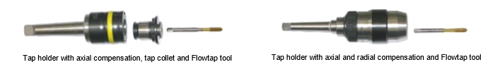
Setup instruction
1. Assembling: tool holder and Flowdrill
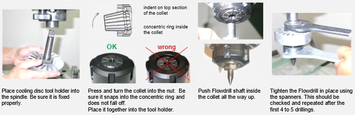
Dismounting:
- When untighten the nut make sure that the Flowdrill does not just fall out, e.g. use a flannel underneath.
- ATTENTION: do not touch the hot drill with your hands!
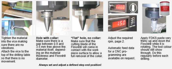
2. Preparation: clamping, stop end position, drilling parameters
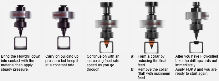
3. Drilling process
4. Equipment for cold form tapping with FLOWTAP:

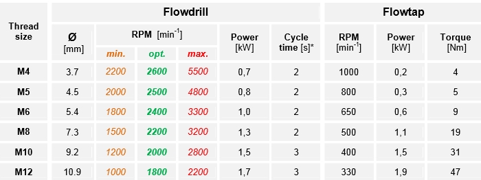
5. Parameters table for FLOWDRILL and FLOWTAP
Note:
- The above table information is recommended standard data. The standard requirements may change with different thread sizes and thread length according to different material thicknesses and specific material properties.
- Stainless steel: 15% less rpm for the Flowdrill process based on the optimal rpm and+0.1mm tool diameter for sizes larger M6
- Aluminum and non-ferrous materials: 50% higher rpm for the Flowdrill process based on the optimal RPM.
- All data is based on 2mmmaterial thickness and optimal rpm-power setting. Each additional Millimeter in material thickness requires approx. +1sfor the processing time.